
From Mesh to BRep Solid in a Few Clicks! Point2Solid Studio Is Making Real Progress
Turning scanned meshes into editable CAD geometry has always been one of the biggest challenges in reverse engineering. Point2Solid Studio is taking significant steps towards making that process faster, easier and more accessible.
We’ve been working hard on Point2Solid Studio, our Windows desktop application designed to transform STL and PLY mesh models into usable OpenCascade BRep CAD geometry, ready for export as STEP files.
And the latest development builds are showing some very encouraging results.
It’s More Than Just Converting an STL to STEP
There is an important difference between putting a triangulated mesh inside a STEP file and actually reconstructing a model using proper CAD surfaces.
A mesh consists of thousands, sometimes hundreds of thousands, of triangles. While those triangles can describe the shape of an object, they aren’t the same as the mathematical surfaces used by traditional CAD software.
Point2Solid Studio is designed to go further.
Instead of simply wrapping the original triangles in a CAD file, the software analyses the mesh and attempts to identify its underlying engineering geometry, including:
- Planes — flat faces and machined surfaces.
- Cylinders and bores — holes, shafts and cylindrical features.
- Cones and tapers — changing diameters and tapered surfaces.
- Fillets and rounded transitions — curved connections between surfaces.
- Native NURBS surfaces — more complex smooth CAD surfaces that cannot always be represented by simple cylinders or cones.
Where reconstruction is supported by the measured source geometry, Point2Solid can replace triangulated regions with genuine CAD faces.
Where a feature cannot yet be reconstructed reliably, the software can retain source-faithful faceted geometry rather than inventing an inaccurate analytical surface.
That distinction is fundamental to what we’re building.
Geometry Recognition Is Getting Smarter
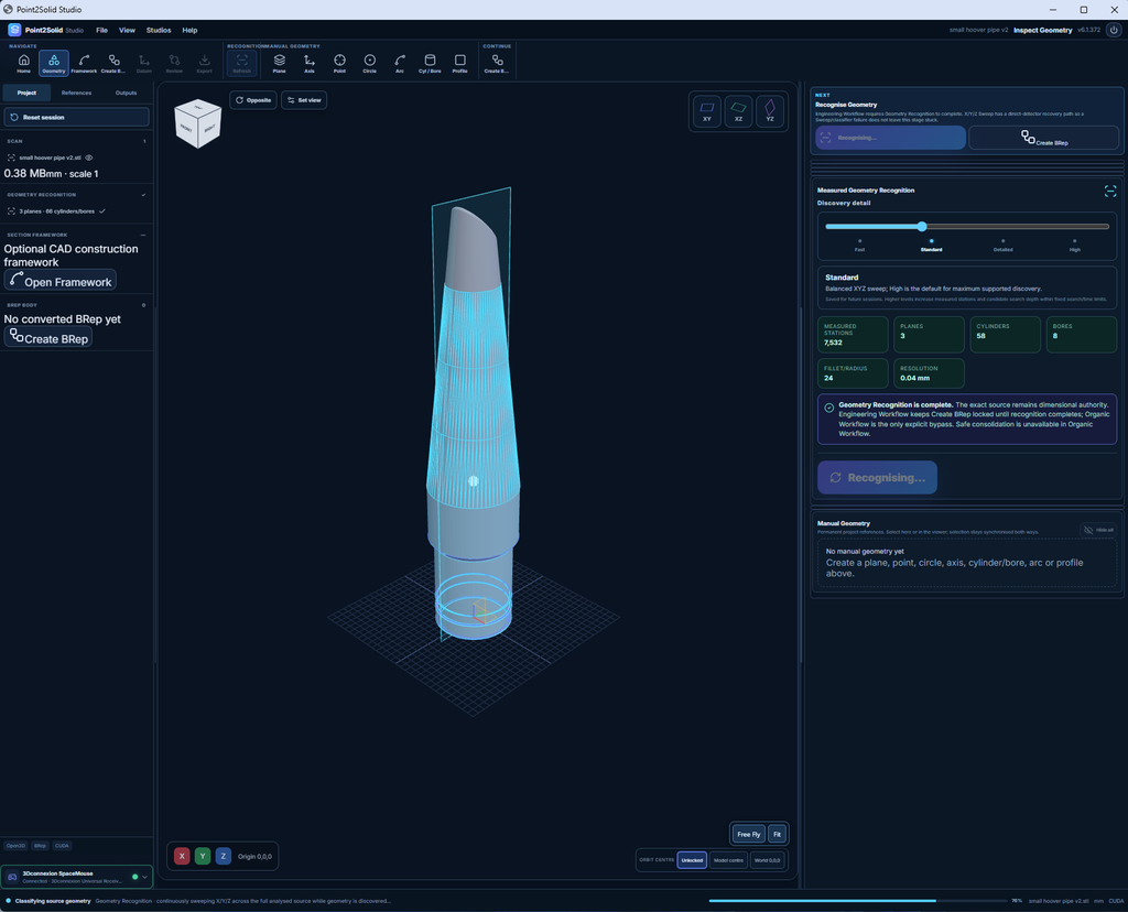
One of the biggest areas of recent development has been the Geometry Recognition engine.
Early versions could identify some basic engineering features, but more complex objects exposed the limitations of automatic surface recognition.
A model might contain several cylinders, tapered sections, small radii and intersecting surfaces, yet only some would be detected correctly.
We’ve been improving the process through more detailed analysis of the source mesh, XYZ cross-sections, engineering-feature discovery and analytical surface fitting.
The objective is to identify not just what type of surface exists, but where that surface begins, where it ends and how it connects to neighbouring geometry.
This matters particularly for parts containing multiple bores, stepped diameters, angled openings, tapered pipes and rounded edges.
The improvements are helping Point2Solid recognise and reconstruct a wider range of mechanical geometry, while retaining strict checks before accepting the resulting CAD model.
A Real Breakthrough With Curved Surfaces
<text></text>
One of our recent test models is a small angled pipe featuring cylindrical walls, a sloping opening and rounded transitions around the end.
This has been a particularly useful challenge because the end geometry includes more than straightforward cylindrical faces.
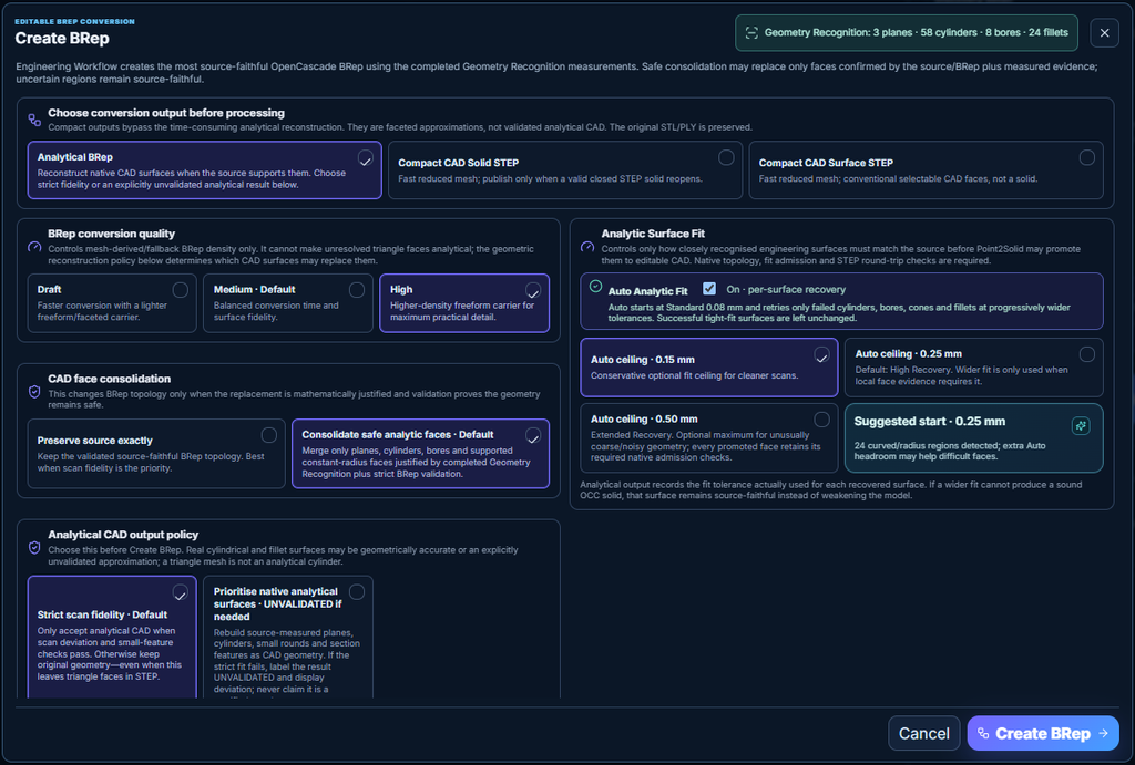
Recent builds successfully produced a validated BRep containing genuine native CAD surfaces, including NURBS blends around the angled opening.
We also resolved a frustrating display issue.
Although the exported CAD surfaces were smooth, the Point2Solid viewer was still drawing the original triangle edges over some analytical fillets. This made the reconstructed model appear faceted even when the underlying BRep contained proper smooth geometry.
That problem has now been corrected.
The viewer can now display the reconstructed surfaces as smooth CAD geometry, with their genuine analytical boundaries, without incorrectly overlaying mesh triangles on verified native surfaces.
This is an important improvement because what users see in the viewer should accurately represent the CAD geometry they have created.
From Mesh to CAD — Then Put the Origin Exactly Where You Want It
Another important part of the Point2Solid workflow is the ability to position the finished model correctly.
Converting a mesh into CAD geometry is only part of the job. To make the model useful in engineering software, you often need to establish a meaningful origin and coordinate system.
Point2Solid Studio includes a dedicated Final Alignment & Datum workspace.
Users can define the origin using recognised engineering features such as bore centres, circular references, edges, planes and selected points.
The model can also be aligned with the world X, Y and Z axes.
For example, you might want to position the origin at the centre of a cylinder bore, align the main bore axis vertically, and export the completed solid in that coordinate system.
This avoids having to perform all the positioning work again after importing the STEP file into another CAD application.
The latest validated workflow also preserves the native CAD geometry through datum positioning and export.
Testing More Complex Mechanical Models
We’re not limiting development to simple cubes, cylinders or demonstration parts.
We’ve been using a growing collection of engineering test models, including:
- Angled pipes with tapered sections and fillets.
- Parts with multiple cylindrical bores.
- Stepped mechanical components.
- Blocks containing counterbores and threaded features.
- Covers, conduits and other mixed-geometry components.
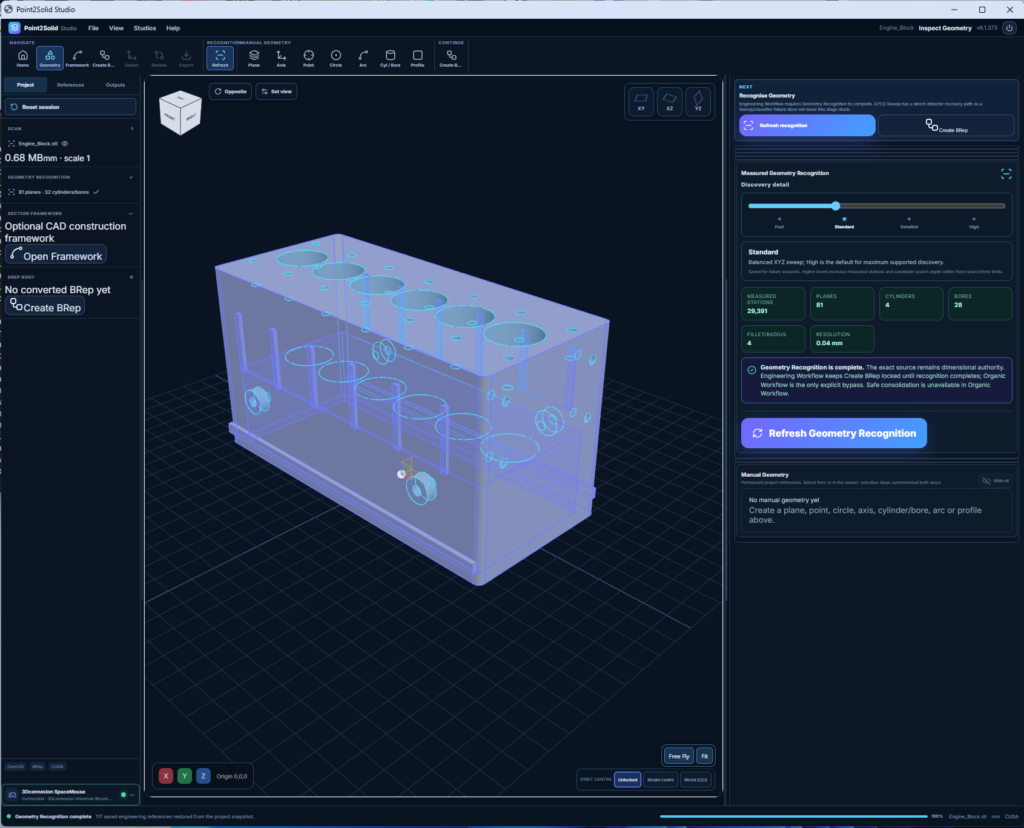
- A six-cylinder engine-block reference model.
These models expose different challenges in geometry recognition, feature boundaries, reconstruction accuracy and CAD topology.
The six-cylinder engine block is a particularly interesting example because it combines several repeated bores with a much more complex surrounding structure.
Testing these more demanding models helps identify where the reconstruction engine succeeds and where additional work is required.
We’re continuing to improve the generic recognition process rather than creating special-case solutions for individual demonstration models.
Real CAD Geometry, Not Just a Convincing Preview
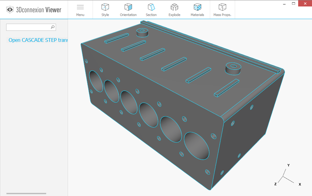
A smooth-looking 3D preview is not enough. BREP STEP Solid Converted from STL
Point2Solid’s analytical reconstruction workflow includes checks on the underlying OpenCascade BRep and exported STEP geometry.
These checks help distinguish genuine CAD surfaces from faceted approximations and verify that the resulting model meets the required topology and reconstruction conditions.
Depending on the source geometry, the result may be a fully reconstructed native CAD solid or a hybrid model that retains unresolved faceted regions.
The software reports these distinctions rather than treating every successful STEP export as proof of complete analytical reconstruction.
Our aim is to produce CAD models that engineers can actually use, inspect and develop further.
A More Complete Desktop Workflow
Alongside improvements to the reconstruction engine, we’ve been refining the overall Point2Solid Studio experience.
The application now brings together the main stages of scan-to-CAD work in one desktop environment:
Import Mesh → Analyse → Recognise Geometry → Create BRep → Review → Set Origin & Alignment → Export STEP
Users can also inspect recognised features, create manual construction references, generate XYZ section frameworks, compare the reconstructed model against the source and save their projects for future work.
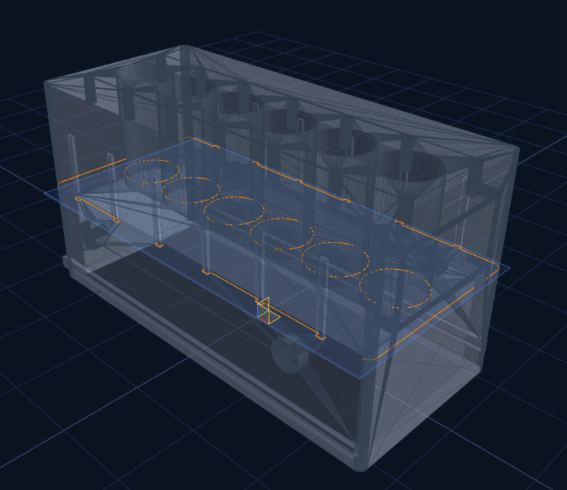
We’ve improved the shaded viewer so original meshes can display their triangle edges by default, with the option to hide them. After BRep conversion, the same display control switches to native CAD boundaries and genuinely unresolved facet edges.
The aim is to make a complex reverse-engineering process feel like one connected workflow rather than a collection of separate tools.
Where Are We Now?
Our latest confirmed working version is Point2Solid Studio v6.1.372.
This version has successfully passed local Windows installer and application testing, including analytical BRep reconstruction and the corrected smooth-surface display.
Development is continuing with v6.1.373, including improvements to session resetting and switching cleanly between different models.
There’s still plenty of work ahead.
Complex surface intersections, very small fillets, difficult scan geometry and reliable analytical reconstruction across arbitrary models remain important development priorities.
But the progress is encouraging.
We’re moving closer to our original objective: taking a scanned or triangulated engineering model and turning it into a useful native CAD solid with as little manual intervention as possible.
The Goal: BRep in a Few Clicks!
Imagine loading an STL file, letting the software discover its planes, bores, cylinders, tapers and fillets, creating a validated BRep solid, positioning the model’s origin and exporting it as a STEP file.
All within one application.
That’s the vision behind Point2Solid Studio.
Mesh to BRep. Recognise. Reconstruct. Align. Export.
And with every successful test and improvement to the recognition engine, we’re getting closer.
Follow our development progress at Point2Solid.com.
Point2Solid Studio is under active development. Results depend on mesh quality, geometry complexity and the availability of sufficient source evidence for accurate analytical reconstruction.
